Introduction
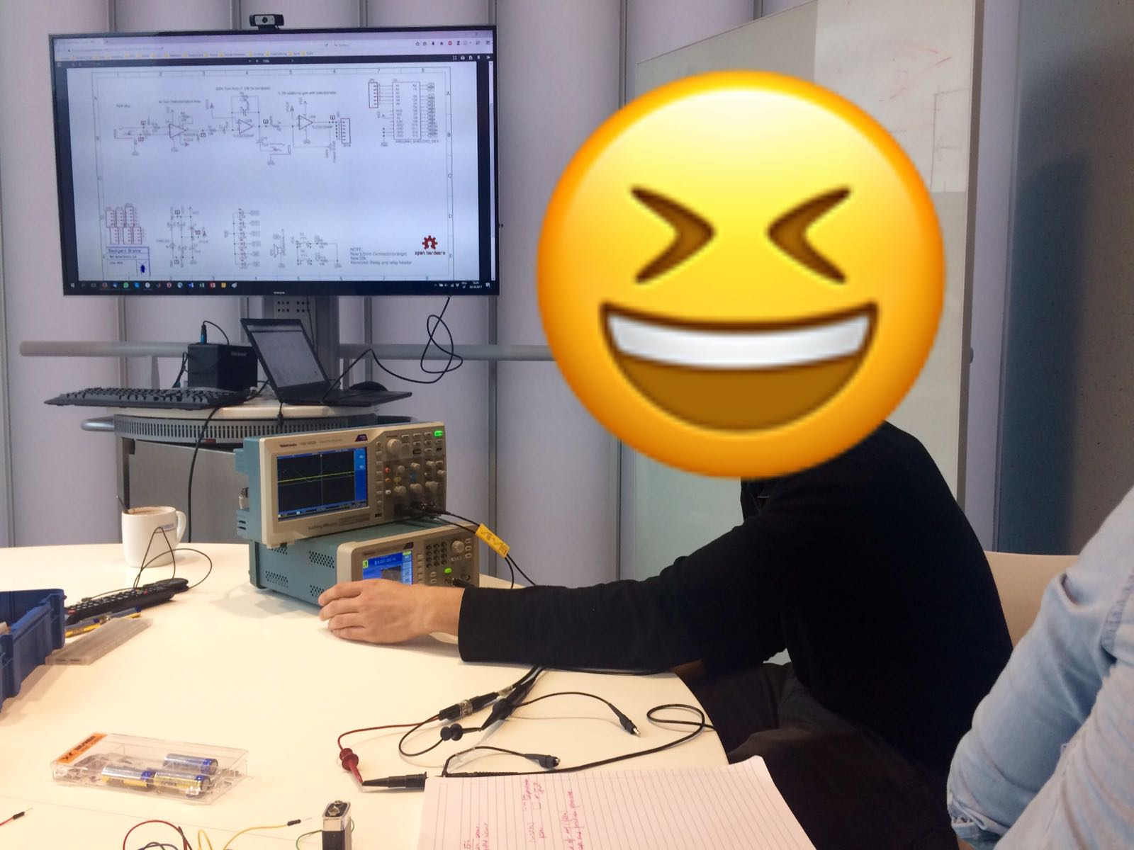
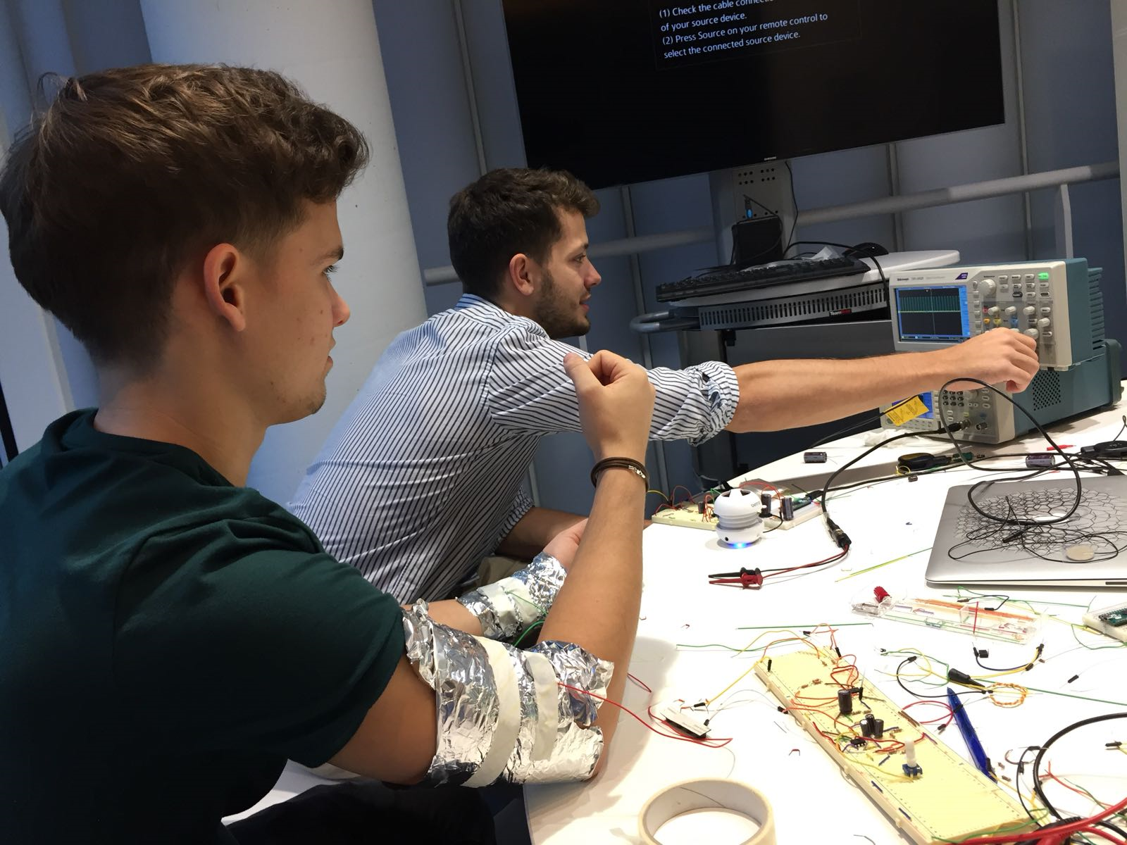
An important tool in Neuroscience is to record brain responses to various tasks and/or stimuli. Presently, there are a few ways to measure brain activity noninvasively, for example: functional magnetic resonance imaging (fMRI), magnetoencephalography (MEG) and electroencephalography (EEG). With fMRI one can measure brain function through detecting changes in the blood flow during neural activity, assuming there is higher oxygen consumption by neurons when activated. An MEG on the other hand captures the magnetic field originating from neural activity. However, we were most interested in capturing the ionic current that flows in neuronal tissue situated on the cortex and results in fluctuating voltage which can be recorded and displayed as electrical activity, and measured with an EEG. In order to record during an EEG, small electrodes and wires are attached to different areas on your head, with some channels serving as reference channels (usually ears and head). EEG allows some relative spatial mapping through the use of multiple channels, however the resolution of time information is rather high. The circuitry within an EEG machine enables the amplification of the detected brainwaves and cancellation of external noise, to achieve a more accurate representation of the ongoing activity. These recorded signals are presented in wave patterns on a computer screen and can be used for further analysis. Similar to EEG is electromyography (EMG), which also measures electrical activity but in the muscles. For the last two weeks our assignment was to build an EEG/EMG circuitry and test it out (on ourselves). By testing out this circuitry we learned more about the communication that goes on between neurons and/or neurons and muscles. After we assembled all the necessary parts and put them together, we were able to listen to electrical impulses produced by muscles at rest and during contraction. When your brain expresses an intent to move a muscle, it cascades a process starting from your upper motor neurons (located in the motor cortex) that synapse with your lower motor neurons (located in the spinal cord) which finally synapse with your muscles (made of many muscle fibers). The release of acetylcholine between neuron and muscle (neuromuscular junction) causes a change in electrical potential which leads to an action potential in the muscle fiber, while this action potential makes its way across the muscle membrane it causes voltage gated calcium channels to open which causes the actual muscle contraction. A muscle contraction is therefore the result of many muscle fibers firing, which is what we record and can display as waves or even sound (if we connect our output signaling to a loudspeaker).
Building an EEG device
Much like our neural systems that are built for sensing changes in the environment, an EEG sensor is comprised of two vital stages: signal transduction and signal processing. We will now look into how these are achieved.
Signal transduction in an EEG
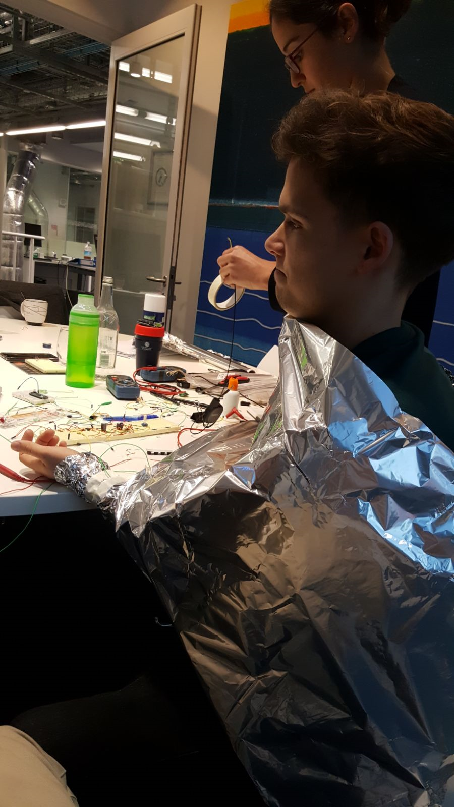
As we mentioned briefly before, an EEG will measure cortical activity. Pyramidal cells make approximately ⅓ of neurons in the cortex, therefore a lot of the action potentials that we measure will largely be based on these cells’ vertically-oriented electrical activity. The signaling from subcortical regions is small since the strength of electrical fields decreases the further it is from the source. However keep in mind that these regions are connected to the cortex through multiple pathways and therefore provide the input to what we are measuring. One of the hindrances for signal transduction with an EEG (for subdural recordings especially) is the hair and epidermal stratum corneum of the skin, but in clinical settings this is solved by removing the hair and making minor invasive incisions. However for regular scalp recordings, you would use a conductive gel or paste to minimize electrode-scalp impedance.
Signal processing in an EEG
The environment around us is filled with electromagnetic activity generated by devices such as our computers and phones. This electrical activity has an associated frequency and amplitude, just like our EEG signal does. As described above, the signals that EEG sensors are picking up from the surface of the skin in response to neural activity are very small values relative to the noisy environment - approximately 1mV. Therefore, in order for us to reliably detect our signals, two processing operations are vital, namely, signal filtering and signal amplification. The net effect of these two operations is essentially to minimise the noise in our signal from the surrounding environment.
Signal filtering
The reason we care about signal filtering is because we are only interested in a particular set of known frequencies occurring at our EEG sensors (fortunately they are already known given the wealth of data in the field of EEG, if we did not know this we could not be confident that filtering would not lead to a loss of information). Because we know our frequencies of interest (approximately 1 – 130Hz) we can build a circuit that will reduce the amplitude of frequencies detected at our sensor not within this range – a process known as filtering. By focusing on the 1-130Hz frequency range we will be able to filter all noise due to mobile phones and internet communication, which occur on the order of MHz and GHz, respectively. Unfortunately, however, we will not be able to filter out a major source of noise for all electrophysiology experiments, the 50-60Hz oscillation due to the main power supply from the national grid. There are two types of filter we can build in an electrical circuit, known as a low-pass and high-pass. A high-pass filter will allow all frequencies above a certain value to pass into the circuit without dampening, thus setting a lower bound, whereas a low-pass filter will allow all frequencies below a certain value to pass without dampening and therefore set an upper bound. Frequencies are changes in voltage with time, therefore in order to affect them within the circuit we need to introduce circuit components that are sensitive to time. The two components we use to achieve this are the resistor and the capacitor. A capacitor is made up of two conductive sheets separated by an insulator that, crucially, will allow current will flow round the entire circuit as they are charging, but current will stop once they are charged. The amount of time it takes for the capacitor to become ‘charged’ depends on two values, the capacitance (C) and the resistance (R). Together, these two quantities generate the ‘time-constant’ (τ), τ = RC. This time-constant is a measure for the amount of time it will take for the capacitor to become charged and discharged (to exactly 63% of its final value to be precise). So, we now have a way of introducing time-dependency into the circuit. Below, we will see how this can be used to filter out signals in a circuit.
High-pass filters (lower bound)
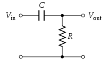
If a frequency is faster than the time-constant of a capacitor, then the capacitor will constantly charge and discharge without ever becoming fully charged, therefore allowing current to flow around the circuit at this frequency. We can hence think of a capacitor as a natural high-pass filter, allowing only those frequencies below its time-constant to be sent to ground. The high-pass filter, pictured below, works by allowing high frequencies from Vin through it, but not allowing low frequencies that have a time-period above its time-constant through it. Again, this time constant is determined by RC.
Low-pass filters
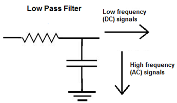
Low-pass filters again harness the fact that capacitors will allow current with a frequency producing a time-period above their time-constant to pass through them. In this case, however, we send the frequencies to ground if they are high, and keep the signals that do not pass through. In this way we get a low-pass filter.
Our 1-130Hz band-pass filter
We constructed a band pass filter by first applying a high-pass filter to our Vin, and then applying a low-pass filter (see picture and video below).
Amplifiers
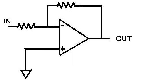
An amplifier is an electronic device that is able to produce an increased output signal, given an input signal. For our setup, we utilized an operational amplifier (OPAMP), which contains two inputs and one output. The function of an OPAMP is to produce an amplified output signal resulting from the difference of the two input signals. One of the inputs is inverting (negative) and the other non-inverting (positive). This is important to know because the goal of an OPAMP is to have both inputs to be of same value. If the inverted input is higher the output will go negative, if the non-inverted input is higher, then the output will go positive. This is why an OPAMP uses the NEGATIVE feedback to control systems while the positive will cause imbalance. The non-inverting input is equal to zero because it is connected to the ground and will therefore force the OPAMP to equal the inverting input to zero as well. This happens with help from the feedback that goes through a resistor and causes the OPAMP to create an output of any current and voltage to achieve the aforementioned balance.
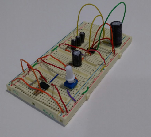
The EEG circuit
Results