Light
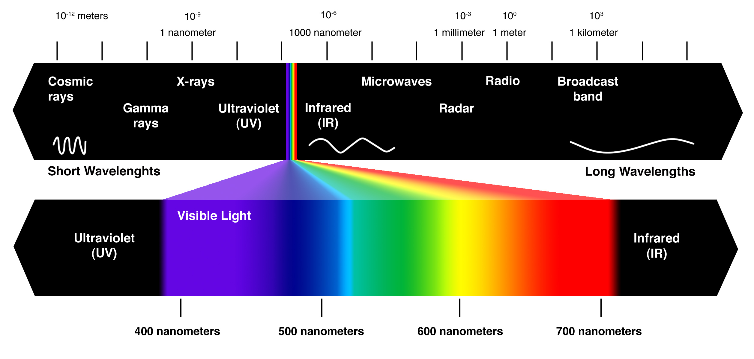
Light is an electromagnetic wave within the spectrum of electromagnetic radiation and usually refers to wavelengths visible by the human eye. The portion of the spectrum defined as visible light ranges from 400 nanometer (ultraviolet) to 700 nanometer (infrared). While the intensity, the wavelength and the polarization of light can greatly vary, the speed of light in a vacuum is constant at approximately and is thereby one of the most fundamental constants of nature.
While the sun, which emits most of its energy in the visual spectrum through the mechanism of black-body radiation, is the main source of natural light on earth, humans engineered several different ways to produce light in order to take advantage of its intrinsic properties. Historically, the most prominent source of light was the flame, which is the visible portion of the rapid oxidation of a material during an exothermic chemical reaction known as fire. Other types of light emission sources were used as for example incandescent light bulbs, in which filaments were heated through the passage of an electric current in order to make them glow with visible light and emit their energy through black-body radiation.
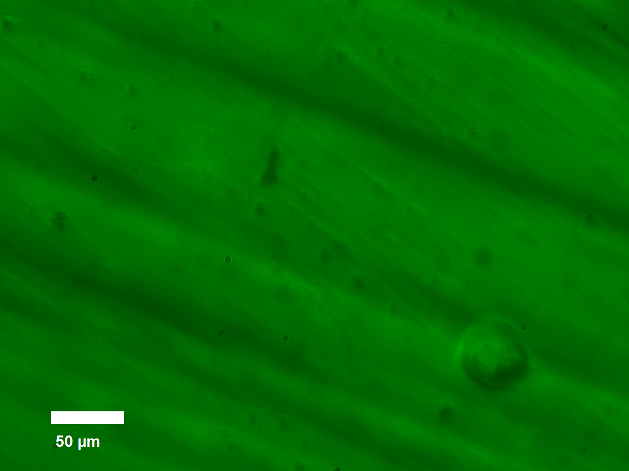
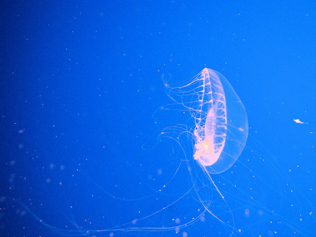
Two other types of light sources with fundamental importance in neuroscience are electroluminescence and fluorescence, which both do not depend on the release of heat. Electroluminescence is an optical phenomenon in which the passage of an electric current or the application of a strong electric field will induce the emission of light from a material, usually a semiconductor. Applying an electric field to a material will excite electrons in the semiconductor triggering their rearrangement thus inducing the release of photons, the quanta of electromagnetic fields. Light-emitting-diodes (LEDs), which emit a narrow spectrum of light when a suitable voltage is applied to its leads, are based on this principle and are now extensively used in neuroscience. Fluorescence on the other hand is the emission of light by a material that has absorbed electromagnetic radiation. The emitted radiation is usually of longer wavelength than the absorbed one, as the energy content of photons is inversely proportional to their wavelength. Several chemical compounds found in living organisms are fluorescent - or biofluorescent - making them ideal targets for usage in Neuroscience - as the famous protein green fluorescence protein (GFP), first isolated from the jellyfish Aequorea victoria in the 1960’s. The original GFP from Aequorea victoria, which is emitting light at 509 nm in the lower green portion of the visible spectrum, has a major excitation peak at a wavelength of 395 nm and a minor one at 475 nm. Since then, other proteins have been found and engineered providing better intrinsic properties as a single excitation peak for example.
Historically, the nature of light was heavily debated and most of the important concepts were formulated during the two last centuries leading to the current view of wave-particle duality. A major breakthrough of 19th century physics was Maxwell’s formulation of four laws describing the behaviour of electric and magnetic fields, shedding some light on the nature of light. Whilst this so-called classical physics description of light has been expanded on by the advances in quantum theory in the 20th and 21st century, Maxwell’s equations still apply and are useful in numerous situations.
Maxwell’s equations describe electromagnetic radiation as oscillations in the electric and magnetic fields propagating in space. But what is a field? A force field describes how a given non-contact force acts on a given particle at various locations in space. This force field gives a vector description of the direction and strength of the force acting on the particle. An electric field would therefore describe the attractive or repelling forces acting on an electron for example.
Maxwell’s equations described how the electric and magnetic fields influence each other as they change. According to Maxwell’s equations, if a magnetic field changes on a plane in space, it will cause the electric field to change proportionally on a plane that is perpendicular to that of the magnetic field.
Specifically, what Maxwell's equations tell us is that when the electric field arrows seem to be forming a loop around some region, the magnetic field will be increasing inside that region, perpendicular to the plane of the loop. And symmetrically, such a loop in the magnetic field corresponds to a change in the electric field, perpendicular to the plane of the loop.
A consequence of this is that an oscillating electric field that propagates in space will produce an oscillating magnetic field that will propagate at the same speed and in the same direction but on the plane perpendicular to that of the electric field (or vice-versa). These propagating electric and magnetic fields are called electromagnetic radiation.
In 1900 it became apparent that there was more to light than the classical physics description of how it works that we outlined so far. When Max Planck attempted to describe the phenomenon of black body radiation, he first suggested the notion of quanta of light. This idea referred to the observation that light waves could only gain or lose energy in discrete amounts. The idea of quanta of light was then used by Albert Einstein in 1905 to describe the photoelectric effect - work that was later awarded with a Nobel Prize in Physics. Einstein formulated the hypothesis that light wasn’t made of waves (as we have seen in the previous section) but could rather be described as both particles and waves, property known as wave-particle duality. The work of Planck and Einstein led to a revolution in modern physics and the formulation of quantum mechanics.
Lenses
Lenses are curved glass surfaces that bend light by refraction. The amount by which light is bent by a lens depends on the speed of the light inside the lens and outside the lens. The angle at which the light exits the lens also depends on the angle at which light went into the lens relative to the curvature of the lens.
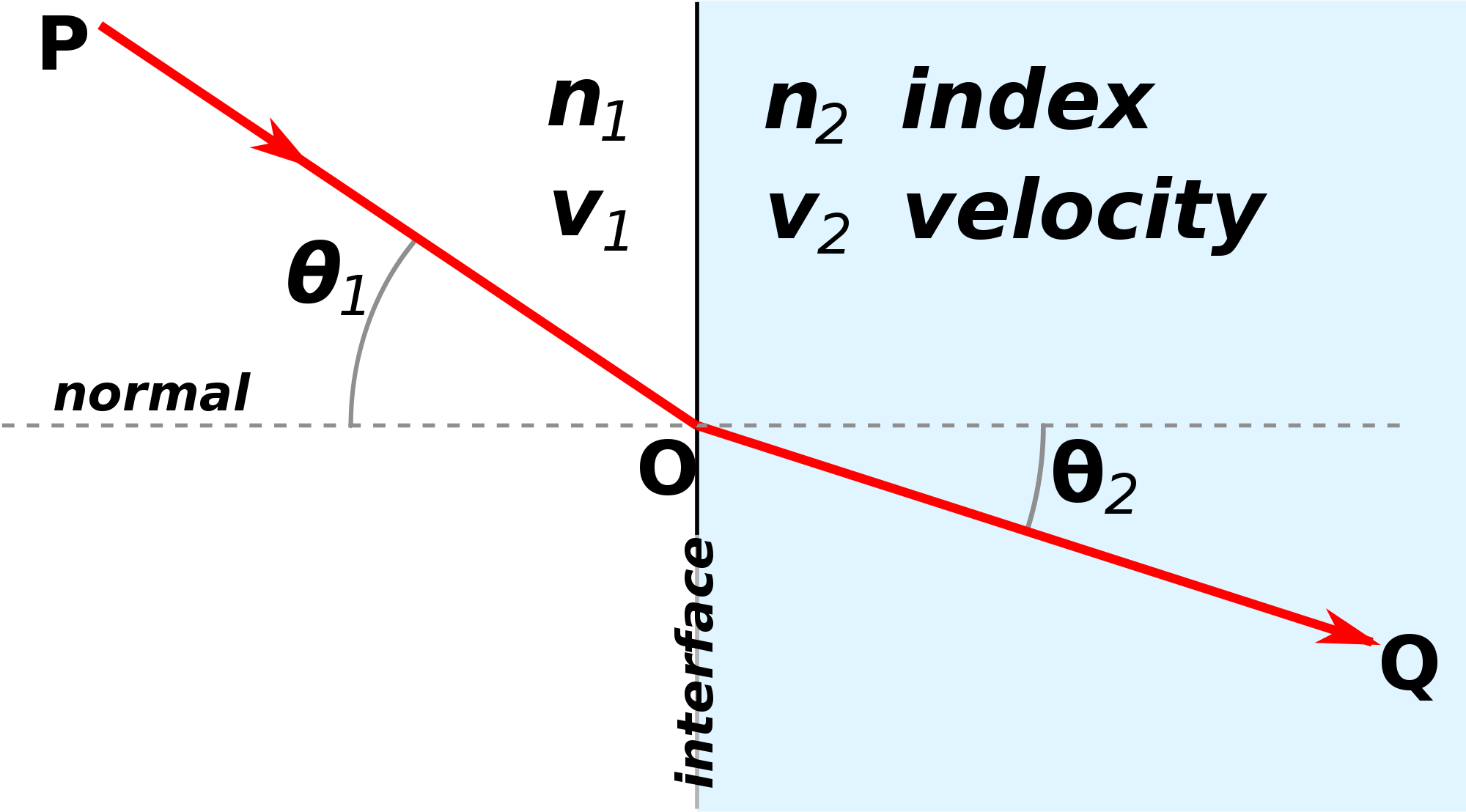
The fundamental formula used to describe the incidence and refraction angles of a ray of light are given by Snell’s law: , where the angle of incidence θ1 and the angle of refraction θ2 are linked to the respective indices of refraction n1 and n2 or equivalently to v1 and v2, the speed of light in the given medium.
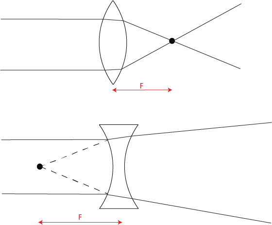
Shining light through any two media that have different refraction indices will cause refraction. Lenses come in two different classes: convex and concave. A convex lens will cause collimated light to converge to a point at its focal point, whereas collimated light passing through a concave lens will diverge.
Microscopes
A microscope is a tool which enables an image to be magnified using a series of lenses. A large variety of microscope types exist using different lenses, distance between lenses and illumination methods. Here we will summarise the types of microscopes that we have built and the differences between them.
The simplest type of microscope consists of one convex lens. If an illuminated object is placed between 1x and 2x the focal length (F) away from the lens, a magnified image will form on the other side of the lens. If the object is placed exactly 2x the focal length away, an image of the same size as the original object will form. If the object is placed further from the lens than 2x the focal length, the image will be smaller than the original object.
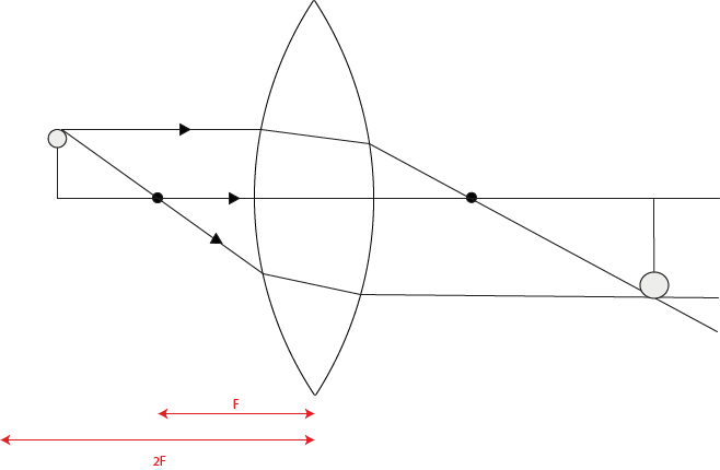
In all cases the real image is inverted. The magnification of the image is given by the ratio between the distance from image to lens and the distance from object to lens. The distance of the image from the lens can be calculated by: .
In addition to the sample and the lenses, the last main component of a microscope is the sensor or detector, on which the image is formed. This can be your eye or a camera sensor. Detectors are usually charge-coupled device (CCD) cameras which convert the detected photons into a digital signal and have nowadays very high spatial and temporal resolution. The CCD-based cameras act as a densely packed array of photodiodes on a chip, where each diode represent a pixel in the output image.
1) Transmitted light Microscope
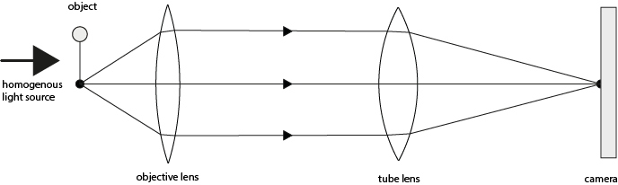
A transmitted light microscope is infinity corrected, meaning it converts divergent light into collimated light before focusing light onto a photosensitive material (such as a CCD or a retina).
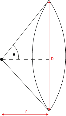
Infinity corrected microscopes use two lenses: an objective lens and a tube lens. One of the advantages of this system is that it does not matter at what distance the tube lens is placed relative to the objective lens. Therefore the magnification of this system is determined by the ratio of the focal length of the tube lens to the focal length of the objective lens. The resolution limit (the minimum distance at which you can reliably tell two dots apart) is related to the diameter of the lens and the longest wavelength of light used:
Where n is the index of refraction, θ is the maximum angle (relative to the midpoint of the lens) at which light can be focused by the lens. Due to geometric constraints, θ is determined by the lens diameter (D) and the focal length (F).
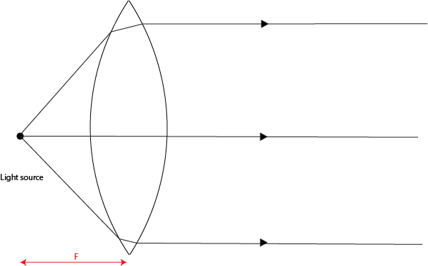
Transmitted light microscopes require the light source to be homogenous. This can be achieved using Köhler illumination or a condenser lens. For our microscope we placed a light source at the focal length of a convex lens, resulting in parallel light rays leaving the lens.
As the light source is placed behind the object, the opaque or translucent object is dark in the image and transparent regions are bright.
2) Dark field/oblique microscope
The dark field microscope operates on principles very similar to those of the transmitted light microscope. In fact, the setup of the optic components is identical between the two, the only difference being the location of the light source relative to the sample. In a dark field microscope the light source is placed to the side of the sample instead of behind it.
In this configuration, when using a semi-transparent sample (like most biological tissues), most of the light will simply travel through the specimen and thus never reach the sensor. The only light reaching the sensor is that which was diffracted by the specimen. As light travels through a biological sample it will cross many interfaces which have different refractive indexes, this will cause light to diffract. Furthermore, if a dye is present, light may also be scattered. Part of the light that will be bent from its original path through these interactions will enter the optical system and form an image of the sample. Thus, in dark field microscopy, the image will have a dark background (remember, most of the light simply travels through the sample) while the object will look bright (as that is where light is diffracted).
3) Fluorescence microscope
Fluorescence microscopes exploit the fact that some molecules, when excited with light of a specific wavelength, emit light of longer wavelength. This allows to image the parts of the sample containing the fluorescent molecules with very high contrast: all collected light will be emitted by the fluorophore and parts of the image not containing the marker will thus be completely dark.
The optics of a fluorescent microscope are arranged exactly in the same manner of those of an infinitely corrected bright field microscope, however the way the sample is illuminated differs significantly. This has to do with two consequences of using fluorescent molecules:
1)Fluorophores need to be excited with light of a particular wavelength to be able to emit light at another frequency, therefore specific light sources and color filters need to be used to make sure that most of the light hitting the sample will be in the right wavelength range.
2) Fluorescent samples will generally emit significantly less light than the amount by which they were excited. Thus, to make sure that the contrast of the obtained images is sufficiently high some strategies need to be implemented to maximise the amount of collected light.
The light source of fluorescent microscopes can either be LEDs of specific wavelengths or lasers. In both cases, a light source should be selected that in order to excite the fluorophore at the right wavelength. To avoid that a significant fraction of emission light is reaching the sensor and thus reducing the contrast, the light source should not be placed behind the sample. By taking advantage of the intrinsic properties of a dichroic mirror, which is inserted between the two lenses at an angle of 45° to reflect the excitation light towards the objective lense, the light source can be placed outside of the optic path thus avoiding direct illumination of the sensor. Dichroic mirrors are very accurate color filters which let selectively pass only a small range of colors while reflecting all others. This filtering step drastically reduces the fraction of excitation light which might reach the sensor after being reflected by the sample.
Generally speaking, the excitation light will reach the sample, excite the fluorophores, which will emit light at a longer wavelength. This light is then captured by the microscope and reach the sensor (as it can pass the dichroic mirror without being reflected). The main consequence of this setup is an increase in signal-to-noise ratio as most of the excitation light will travel through the sample and not reach the sensor. The usage of a color bandwidth filter just after the light source (transparent only to the excitation wavelength) and one close to the sensor (transparent only to the emitted wavelength) will further increase the signal-to-noise ratio.